Assembly #
Please follow the instructions below carefully to install the Nozzle Magazine to your SMT machine. The Nozzle Magazine mounts to 2020 aluminum extrusions using T10 screws with insert nuts. View the linked PDF below.
Wiring #
You can wire both limit switches together to a single endstop on your controller by bridging them together or wire each limit switch separately to your controller. For the purpose of these instructions, we will be wiring both together to a single limit switch as shown below.
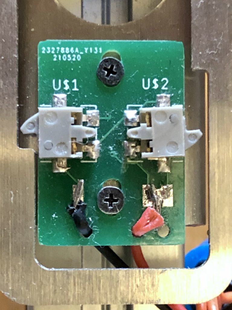
NOTE: Make sure to add reverse diode protection to the motor to protect your controller if you don’t have one already on your controller board!
Motion Controller Config Setup #
For the purposes of these instructions we will be setting this up in Smoothieware. Copy the below config example and modify the pins to suit your controller.
# NOZZLE MAGAZINE

switch.nozzlemag.enable                               true      # Enable this module
switch.nozzlemag.startup_state                        false
switch.nozzlemag.input_on_command                     M804      # Command that will turn this switch on
switch.nozzlemag.input_off_command                    M805      # Command that will turn this switch off
switch.nozzlemag.output_pin                           1.0       # Pin this module controls
switch.nozzlemag.output_type                          digital   # PWM output settable with S parameter in the input_on_comand

switch.nozzlemagendstop1.enable                       true
switch.nozzlemagendstop1.input_pin                    3.25^
switch.nozzlemagendstop1.input_pin_behavior           momentary
switch.nozzlemagendstop1.output_on_command            M805

switch.nozzlemagendstop2.enable                       true
switch.nozzlemagendstop2.input_pin                    3.26^
switch.nozzlemagendstop2.input_pin_behavior           momentary
switch.nozzlemagendstop2.output_on_command            M805
OpenPNP Setup #
The Nozzle Magazine is designed to be set up the same as any other nozzle magazine for OpenPNP. No special scripts are needed. Full OpenPNP Nozzle Tip Changer instructions can be found here, but we recommend you follow our instructions below, which are tailored to our product.
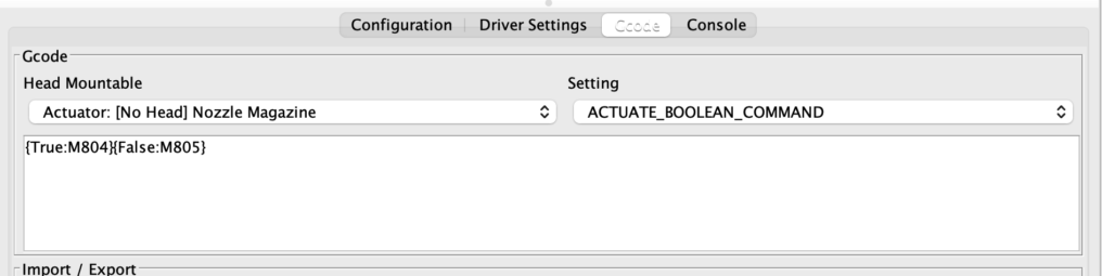
Set up a new Actuator named Nozzle Magazine and then navigate to your motion controller driver of choice that will manage the nozzle magazine and add {True:M804}{False:M805} under the ACTUATE_BOOLEAN_COMMAND setting and click save.
Next, we need to make sure the magazine opens fully and closes. Slightly un-tighten by just a few turns the two screws holding the PCB so you can move it freely as shown below left to right.

Next, adjust the PCB by moving it very slowly to the left or right and re-tighten the screws (don’t over tighten or you will strip the screw threads!) while toggling the nozzle magazine actuator ON in the jog panel under Actuators > Nozzle Magazine. If the motor on the nozzle magazine does a full 360o rotation and the cover returns to the same position, it means that one of the end stops isn’t being triggered because the cover cannot reach it. Re-run the adjustment until the cover only opens or closes the nozzles whenever you the Nozzle Magazine actuator ON.
Make sure that the cover is fully open and not partially open! Nozzles should be able to drop in easily.
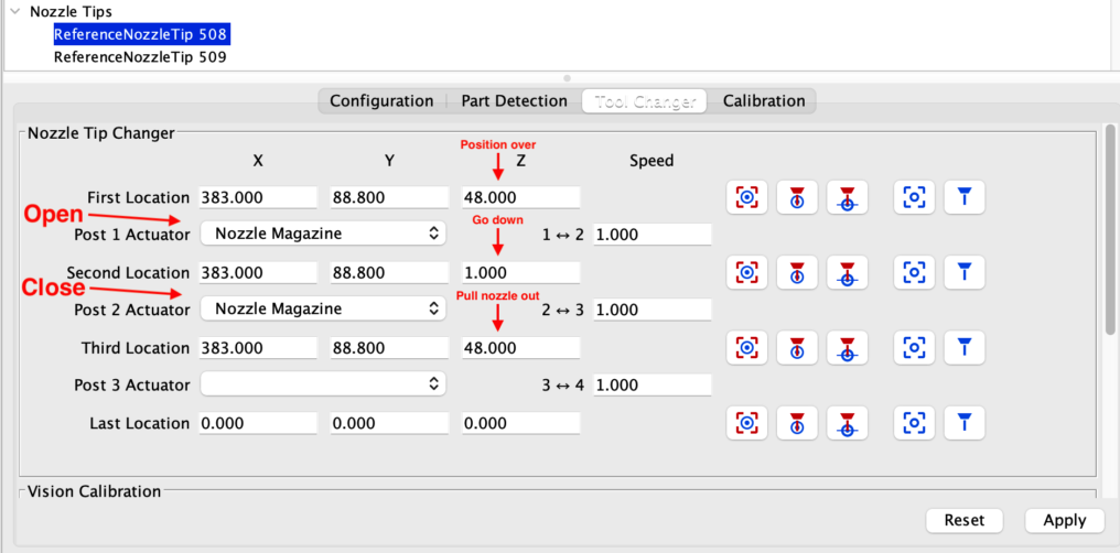
Now that we’ve got the magazine opening and closing the cover properly, we need to adjust the X & Y coordinates in OpenPNP for each nozzle so that the head can pick them up smoothly without crashing into it. Unload all the nozzles from the head to make sure you don’t crash any into the magazine. Navigate to Machine Setup > Nozzle Tips > Click on the first ReferenceNozzle > Tool Changer as shown below.
The distance between the nozzles is 21 mm and there are a total of 10-20 nozzle holders depending on the size you have.
Because these X, Y & Z coordinates vary machine to machine, you need to tune it. If you haven’t loaded the magazine with nozzles, now’s the time to do so. It’s ok if you have empty holders in the magazine. We just need to test the first few holders on one side and you can then copy the settings and adjust the coordinates.
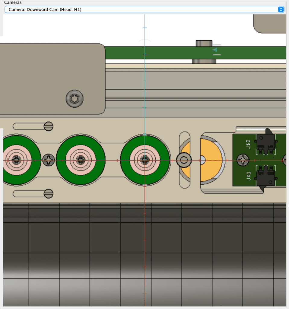
Home the machine in the jog panel. Select the Down Camera from the cameras dropdown on the jog panel so you can view it and jog it so the crosshair sits directly over the first nozzle as shown below.
For the first location, click the capture camera position icon and the XYZ coordinates will update. Next, click the “position tool over center of location” icon on the first location settings and move it down in Z until the head clicks into the nozzle. Click “capture tool location” icon to update the Z setting for the second location.
You’ll notice that only the Z changes. For the third location, you can just update the Z to match the first location. Subtract/add 21mm for the next nozzle for either X or Y (depending on how you mounted it) and repeat the process slowly to ensure that your nozzle magazine is mounted square to your machine.
Before using the nozzle magazine in a production run, test it out by turning the actuator on/off manually to pull the nozzles off the head.
Failure to test the magazine with all holders manually can cause your head to either crash the nozzle into the magazine or jam the cover over the nozzle!
Common issues & solutions #
- Motor cam is too fast and overshoots position, therefore unable to have the cover fully open!
Due to mechanical inertia of the motor, the cam can overshoot the cover and leave it partially closed, enough to jam the nozzle. To overcome this, you can add a delay in the ACTUATE_BOOLEAN_COMMAND as shown below. Note that this requires the motor to be driven by an H bridge driver (DRV8833 for example) to be able to reverse direction of the motor in order to brake it. Replace Mxxx with your choice of command.M804 # Turn on pin for CW direction
Mxxx # Turn on other pin for CCW direction
G4 S1 # Run Mxxx for 1 second (G4 is a smoothie command)
M805 # turn off Mxxx pin and stop motor completely - Motor cam is too slow to my liking. Make it go faster!
Our recommended voltage for the motor is 5v, although the motor is rated for 6v. To make it go faster, you can increase the voltage to 12v for example. This will not harm the motor as it is only turned on intermittently for a few seconds. Note that at increased speeds, you may need to add the braking suggestion listed above and tune the G4 time.
You can also alternatively source a higher speed motor for your voltage with a different gearbox ratio. Note that faster motors typically have a smaller gear box and are therefore weaker. The motor shaft diameter & length used is a common dimension.


