Designing the extension(s) #
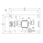
If you’re using the Mini Motherboard, you will need to create an extension of the RS485+ and RS485-. You will also need to use an external 5V power supply rated for at least 10A (for safety). On the extension board, the traces the feeders plug into must be 60 mil wide and 2.5 mm pitch. From top to bottom the traces should be 5V, RS485+, RS485- and GND. You should design your extension with a screw terminal to plug your 5V supply into to power the feeders directly. Make sure your screw terminal’s legs don’t protrude where your feeders mount.
Power consumption (minimum):
0.055 Amps @5v per feeder when idle
0.26 Amps @5v per feeder when both motors working same time.
2.75 Amps @5v for 50 idle feeders.
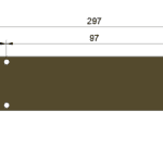
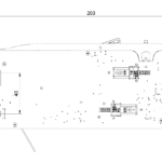
Take into consideration how you will mount the extension to your machine so that when the feeders are mounted, the feeders’ spring connectors sit exactly over the traces and that its’ contacts don’t touch adjacent traces. Take special note of the 14mm distance as indicated on the feeder drawing below. This is the distance the feeder should mount from the underside of a 1.60mm thick PCB.
Use the drawings below for reference and the 3D STEP files for assistance in checking your setup in your CAD program.
The pick location for the feeder is the bottom of the box cutout on the top of the feeder. That represents the top of the SMT tape and exposed window for the tape.
DOWNLOAD 3D STEP FILE – 8MM FEEDER
DOWNLOAD 3D STEP FILE – MINI RAPID FEEDER MOTHERBOARD
If you’d like to have feeders on all four sides of your machine, you can do that by connecting all four extensions in series. Do not connect extensions in parallel to the motherboard!
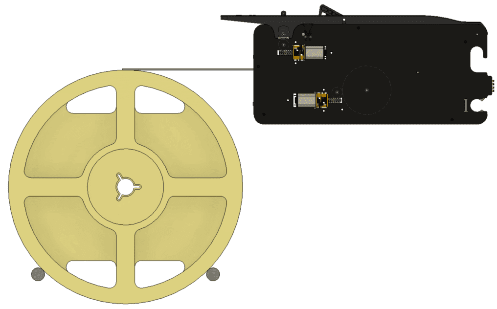
Mounting the spool #
There are many ways you can go about mounting the spool. We recommend using two rods spaced 45 degree apart from the center of the spool and having the spool rest on the rods as shown below. Whichever way you choose to setup your spool holder, make sure the spool sits level to the feeder tape entry or under so that it’s easy for the feeder to pull the tape in. See the recommended setup below.
Testing your setup #
When you test your setup for the first time, we recommend only mounting one feeder to test first. This way, if you mis-wired something, you won’t damage all of your feeders. You should mount it with the power off for the first time to first check that everything lines up mechanically. Do this on both ends of each feeder bank to ensure the rods are aligned on each end.
When you mount the feeders for the first time, the routed cutouts on the front of the feeder may have a tight fit around the 10mm rods. Be sure to push the rods fully into the feeder so the slot can adjust to the size of the 10mm rod’s tolerance. As you use the feeders over time, it will “settle” to smoothly mount over the rods.
After you’ve checked that the traces line up with the spring connector and the distance between the feeder and extension is 14mm as according to the feeder drawing, you can power up the motherboard with ONE feeder loaded.
To test that your 5V and GND are connected to the feeder properly, press the Forward Tape button found on the back of the feeder where tape is loaded. You don’t need to load the feeder with tape for this. If the sprocket starts to advance forward, then your feeder is wired correctly. You can now proceed to the Rapid Feeder Documentation to finish your setup.


