Pre-requisite #
Before you setup your feeders, if you are using the Mini Rapid Feeder Motherboard, then you need to first setup your feeder bank(s). There is a separate documentation page for that product available here: Rapid Feeder Motherboard. Once you finish setting up the motherboard, come back here and follow the rest of this guide. If you’re setting up the feeders on a Rapid Star, you can ignore the motherboard article and continue reading.
Important Notes #
QR Code #
Each feeder ships with a UUID (Universal Unique Identifier) programmed into the feeder as its’ address. This is the code that is on both QR codes visible on the feeder. Do not peel off the QR codes! Should you peel off the QR codes or damage them, you will not have a way to identify the feeder’s address for OpenPNP. This is also the product’s serial number should you ever need to provide it to customer support.
Mounting Feeders #
When mounting the feeders do not slide them side to side! Doing so can damage the spring connector and scratch the motherboard’s traces, therefore reducing it’s lifespan quicker.
Loading Tape #
Coming soon.
Unloading Tape #
Coming soon.
OpenPNP Setup #
(Rapid Star users can skip to the next paragraph) After creating an actuator named Rapid Feeders, create a new sub-driver under GcodeDriver for the Rapid Feeder system named Rapid Feeder Motherboard. Under ACTUATE_STRING_COMMAND add M603 {StringValue} and hit apply. M603 is to advance the tape forward and M602 is reverse.
Note: If you are reversing the feeder via M602 command, make sure your cover is propped open. The 2nd motor that peels the cover does not reverse direction when the sprocket moves backward. Leaving the cover closed and sending M602 will cause the tape’s cover to stretch and possibly break.
To perform an initial scan for feeders, go to the Feeders tab and create a new Rapid Feeder. You should name it something that describes the bank of feeders that it will scan for, such as RapidFeeder-West.
In the settings for the feeder, locate the Scanning section and define the Scan Start, Scan End and Scan Increment values:
Scan Start: When scanning for QR codes, the camera will be moved to this position to start scanning. Move the camera to the location of the first possible QR code and save the location.
Scan End: When scanning for QR codes, the camera will finish the scan at this location. Move the camera to the location of the last possible QR code and save the location.
Scan Increment: When scanning for QR codes, the camera will move by this distance between each image capture. This value should be approximately half the size of the camera image frame. This ensures that the scan will never advance past a QR code and miss it. When the above values are set, press the Scan button. The machine will move the camera along the line formed by the start and end points and capture QR codes. When it finishes it will create or update feeders in the feeder tab for each QR code it finds.
Usage #
Once scanning is complete, pressing the feed button for any of the new feeders will send the FEED command to the Rapid Feeders actuator in the form of {M603 {ADDRESS} {PITCH}}.
LED Indicators #
There are four LED indicators on the back of the feeder. The following is what they signify:
GREEN: Sprocket is moving tape forward
WHITE: Sprocket is moving in reverse
YELLOW: Tape cover motor is peeling the cover off the tape
RED: This indicates that the feeder detected it took too long to peel the tape’s cover. This usually happens when the tape’s cover has broken or was improperly set up. This is followed by an error being sent to OpenPNP to check the feeder’s cover: “Feeder halted. Check tape cover of feeder with red light!”
When the red LED turns on, the feeder is halted and will not accept any new commands. You will need to reset the feeder by either pressing the reset button on the back of the feeder or lifting the feeder slightly to power it off and plug it back in to power it on again. You do not need to do anything in OpenPNP. All your settings will remain the same. This just reboots the feeder.
Resource Files #
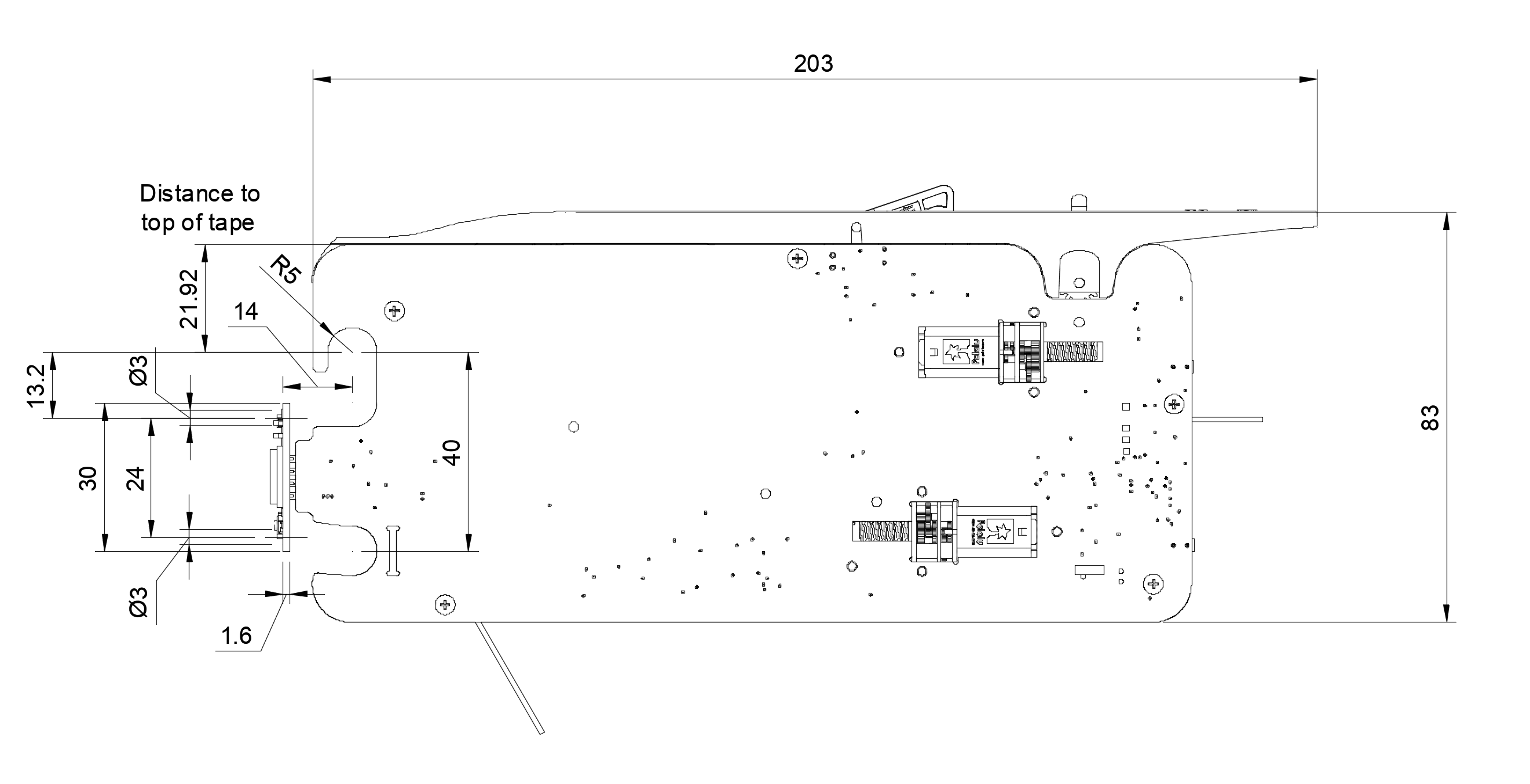
Below is a 3D step file of the Rapid Feeder 8mm version. You can use this to import it into your preferred CAD program and see how the feeder will mount to your machine. It has the four pin spring connector modeled into it as well as the pick location height. The pick location is the bottom of the box cutout on the top of the feeder. That represents the top of the SMT tape. Please also see the attached drawing for required dimensions when mounting the motherboard.
DOWNLOAD 3D STEP FILE – 8MM FEEDER