Introduction #
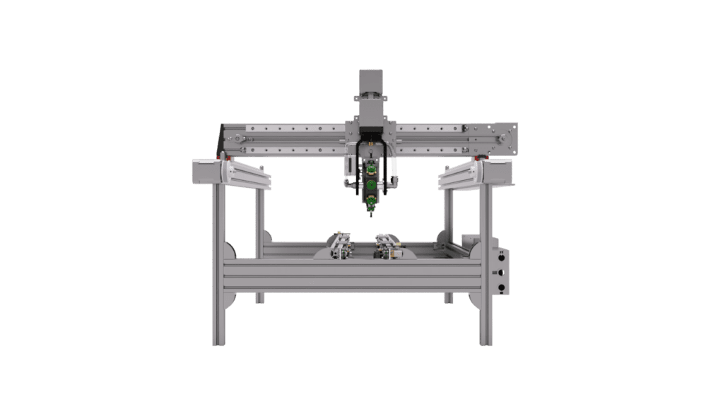
The Rapid Star is a new PNP machine that uses 8 nozzles simultaneously to allow for high CPH (Components placement per hour) output with a conveyor system. The design is very versatile, allowing you to change the setup to suit your needs. The Rapid Star also incorporates our easy to use Rapid Feeder system. The machine is currently in beta testing and will be available to order soon at our online shop. These instructions are preliminary and subject to change without notice before release.
All the required tools are included. There is no soldering or wire crimping required. Here are the tools you will be using:
- T10 screw driver (M3 screws)
- 3mm Hex driver (M5 screws)
- 4mm Hex driver (M4 screws)
- 1.3mm Hex driver (M2 screws)
If you need help with missing or damaged parts please let us know! We are here for you and will be happy to help. Simply click the live chat icon on the bottom right of your screen to talk to us.
And always read the instructions first before starting a step. Images are not enough to follow. We’ve kept the instructions as short as possible. Read them.
Important: Electronics Protection #
 WARNING: Make sure to protect the electronics against electrostatic discharge (ESD). Always unpack the electronics right before you need them!
Here are some tips to prevent damage to the electronics:
- Keep the electronics inside the ESD bag right until you are asked to install them.
- Always touch the sides of the board while working with it. Avoid touching the chips, capacitors and other parts of the electronics.
- Before you touch the electronics use any conductive (steel) structure nearby to discharge yourself.
- Be extra cautious in rooms with carpets, which are a source of electrostatic energy.
- Clothes from wool and certain synthetic fabrics can easily gather static electricity. It is safer to wear cotton clothing.
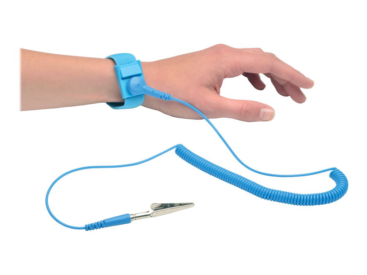
- Best solution is to wear a proper grounded wrist strap.
Machine Assembly #
The below PDF shows how to assemble the machine. Please follow the instructions carefully to ensure you do not make mistakes that can damage the machine during operation or result in inaccurate placement of parts. If you wish, you may download the instructions by clicking the download button on the viewer below.
You can also view the Rapid Star in 3D in your browser or join our Discord server to ask for help.
NOTE: THESE INSTRUCTIONS ARE CURRENTLY A BETA RELEASE AND SUBJECT TO CHANGE/UPDATE.
Find mechanical assembly guide HERE.
Cable Harness Assembly #
User Manual #
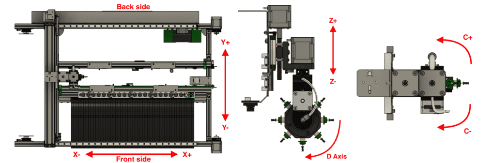
Coordinate System #
All linear axis coordinates (XYZ) are in millimeters and rotational axis such as C and D are in degrees.
Installation #
Download and install OpenPNP.
Download the latest machine.xml for the Rapid Star and replace it with the default one. Make sure OpenPNP is closed while doing this or it will overwrite the file when you close it!
- Mac users:
Navigate to Username/.openpnp2/machine.xml
Tip: If you don’t see the folder .openpnp2 under your username, you’ll need to enable hidden folders. You can do this by holding down ⌘ + ⇧ + . - Windows users: On Windows Vista and above navigate to C:\Users\Username\.openpnp2
Navigate to Machine Setup > Drivers > Gcode Driver Rapid Board > Configuration. Select the port for the machine and baud rate 115200 and click Apply to save the settings. Check that you set up the connection to the Rapid Board correctly by clicking the power icon ![]() . The machine should turn on and the home icon should appear yellow
. The machine should turn on and the home icon should appear yellow ![]() to indicate that the machine hasn’t been homed yet. Don’t home it yet!
to indicate that the machine hasn’t been homed yet. Don’t home it yet!
Note: You need to first power on the machine before you open OpenPNP so that it can detect the cameras. OpenPNP does NOT detect new cameras after it has already been opened. Therefore, before you continue, make sure your machine is on and re-open OpenPNP.
User Interface #
Jog Panel #
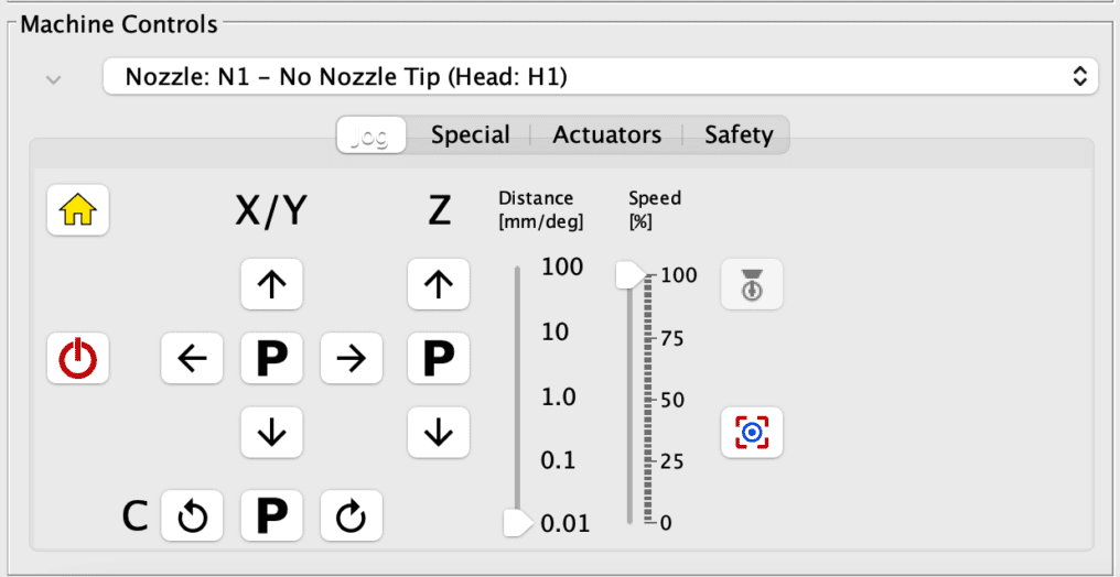
The jog panel is where you control the machine’s peripherals directly. You can:
- Turn the connection to the machine on and off using the power button
 .
. - Home the machine using the home button
 , which you should do each time you power on the machine.
 - Move the machine in the various coordinates using the arrows and rotate the nozzle using the rotation buttons.
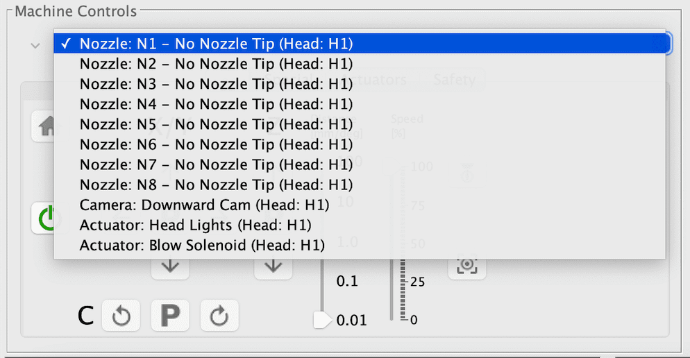
- You can select the active nozzle by choosing it from the dropdown menu.
- Activate various actuators such as vacuum pump, lights, solenoids, conveyors and nozzle magazine manually via the actuator tab.
Digital Read Outs (DROs) #

The digital readouts show where the selected nozzle is located in relation to the machine’s coordinate system.
Camera View Panel #
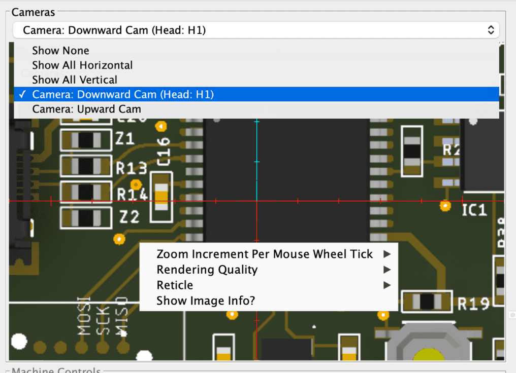
The Camera View Panel is where you can select which camera you would like to look at or alternatively view both cameras at the same time by splitting the view horizontally or vertically. You can choose the different views via the dropdown list on the top. Additionally, you have the option to adjust the crosshair options for the specified camera if you’d like by right clicking anywhere inside the camera view to bring up the options.
OpenPNP Setup #
Machine Checklist #
With OpenPNP installed and the machine settings loaded, now is a good time to check that your machine is properly connected and functioning before we move forward with calibration. Here is a list of checks to perform:
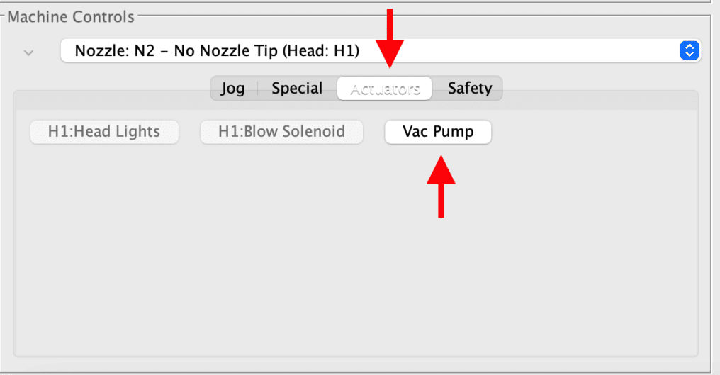
- Actuators: On the jog panel, click the actuators tab. You will now see the Vac Pump, Blow Solenoid, Head Lights, Bottom Lights, Conveyor and Nozzle Magazine actuators. Click each one and check that the machine turns on the individual features when you turn the actuator on/off in OpenPNP.
- End Stops: Navigate to Machine Setup > Drivers > Gcode Driver Rapid Board > Console, enter M119 and click send. You should see a response such as this: X_max:0 Y_max:0 Z_max:0 B_min:0 C_min:0 If one of the end stops shows 1 instead of 0, check that the end stop isn’t mechanically triggered and re-run the command. The status should change from 1 to 0. Now, manually by hand press the XYZC end stops one by one and send M119 command. You should see the status change from 0 to 1 for each one while it is clicked. For C axis, rotate the fork clockwise to trigger. For D axis simply rotate the octagon so the pin is inside the optical slot sensor and check that the status changes. Make sure the changes correspond to the actual axis. For example, if you are manually triggering the X endstop, but the console shows Y is being triggered, it means you have mis-wired the end stop connections.
- Air Leaks: Disconnect the 8mm tube from the Z bracket and turn on the vacuum pump just like you did in the actuators tab before. Now block the tube with your thumb. The pump should change its sound and run almost silently because the tube is blocked. If you can still hear it producing the same noise level without any change, it may mean that one of the tubes isn’t pressed in well and there is an air leak.
- XYZCD Moves: Click the home icon on the jog panel. The head should home to the top right and so will the Z, C, D axis. After it’s done, the head will move to the bottom left of the machine. If this does not happen, it could mean that it was not able to home one of the axis. Check your end stop connections again if that is the case.
- Belt Tension: Place the Calibration PCB that was included with your kit in the middle of the conveyor so it is held in place with the square copper cutout facing up. Jog the machine so that the downward camera is on the center of the fiducial. Now jog in X 10mm to the left and then 20mm to the right and then 10mm back to the left. Check that the camera’s crosshair has arrived back in the same position. If not, you may need to tighten your belt slightly, but do not over tighten or you may risk bending the motor shaft! Do the same for the Y axis. To make sure the precision is really tuned, position the camera over the fiducial again and jog with the distance set to 0.10mm. If the crosshair does not budge right away when you jog once, some more tightening of the belts may be required. The head needs to be sensitive enough to react to 0.10mm moves at least.
Nozzle Vertical Calibration #
*coming soon*
Cameras #
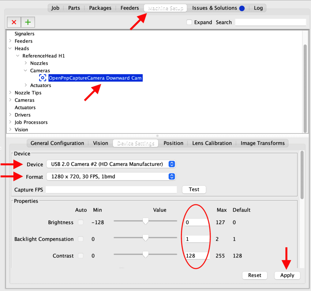
Note that if you do end up connecting the Rapid Star to a different USB port on your computer, the camera device settings are lost and you will need to set this up again. It’s recommended that you set this up on a USB port that you intend to use permanently!
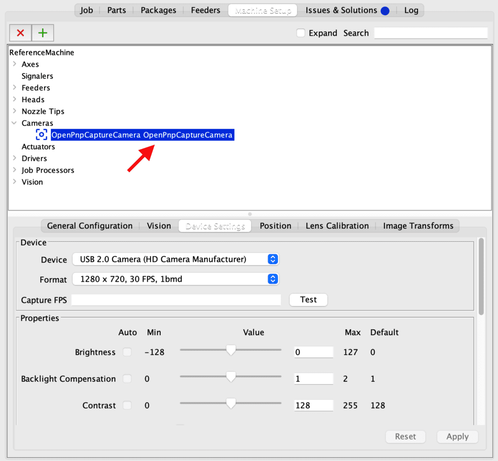
While most of the Rapid Star’s settings have already been pre-configured for you, we still need to calibrate it. Navigate to Machine Setup tab > Downward Cam. Select the camera on the head and choose the same 1280 x 720, 30FPS, 1bmd resolution settings as shown in the image below. Make sure all the settings for the specific camera such as brightness, backlight compensation, contrast, etc. are the same as those listed under the default column and click apply to save the settings. Check that you selected the correct camera by waving in front of the camera and seeing if it shows up on the dashboard to the left when the downward cam is selected.
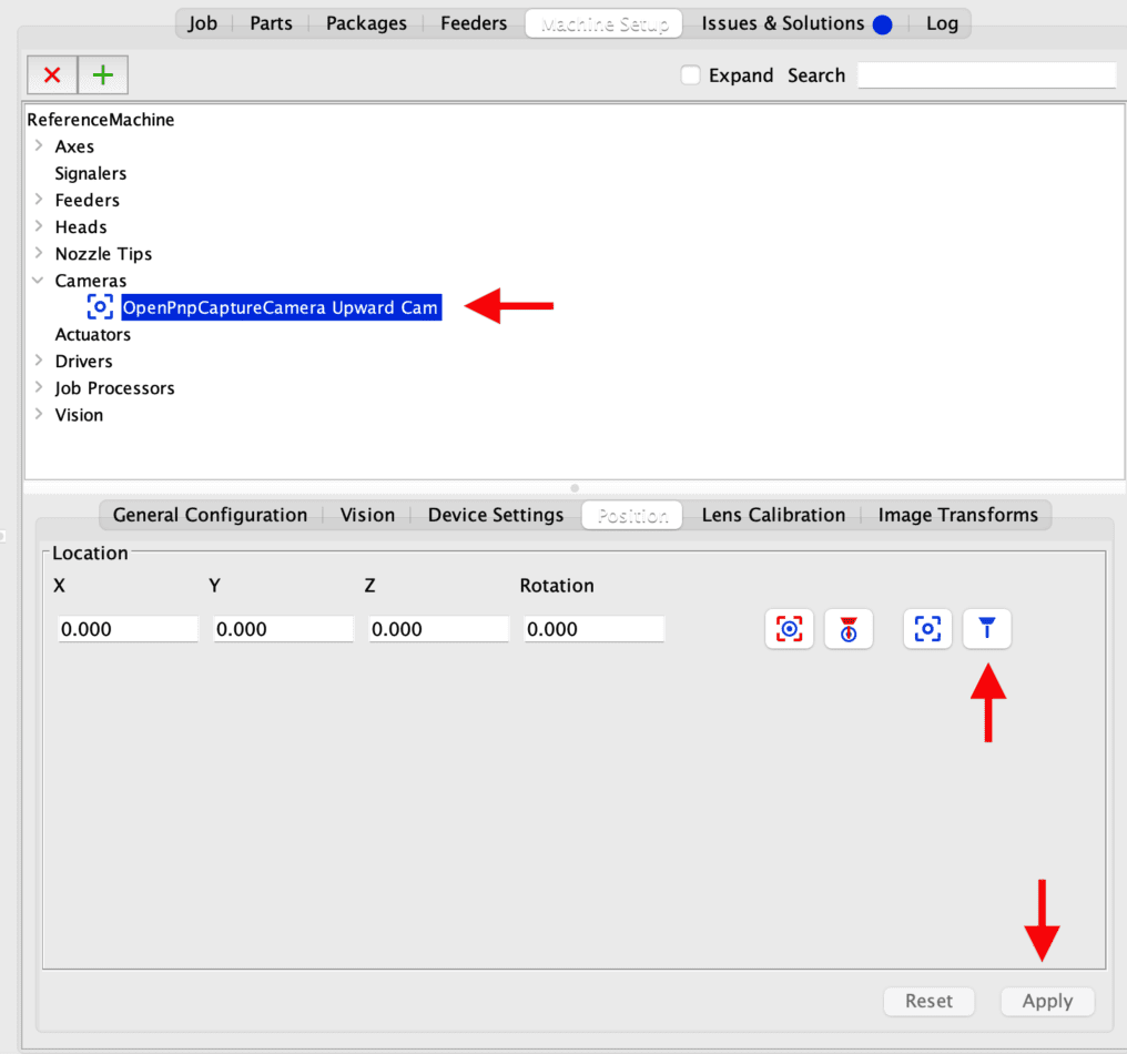
Do the same for the Upward Camera listed under Machine Setup > Cameras.
Next we will capture the position of the cameras. We will start with the upward looking camera. Home the machine ![]() and then jog the selected nozzle (XYZ) so that it is perfectly centered and in focus over the camera. Navigate to the position tab under Machine Setup > Cameras > Upward Cam > Position and click
and then jog the selected nozzle (XYZ) so that it is perfectly centered and in focus over the camera. Navigate to the position tab under Machine Setup > Cameras > Upward Cam > Position and click ![]() capture nozzle icon. You will see the location coordinates update.
capture nozzle icon. You will see the location coordinates update.
Lens Calibration #
Upward Looking Camera #
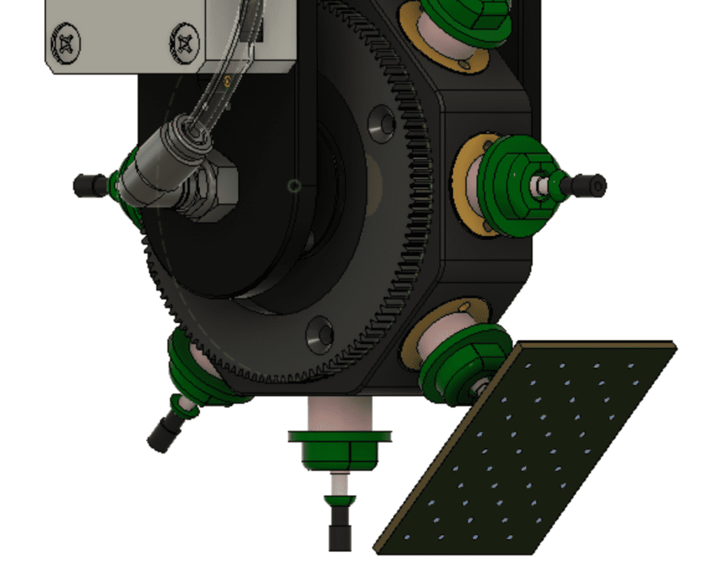
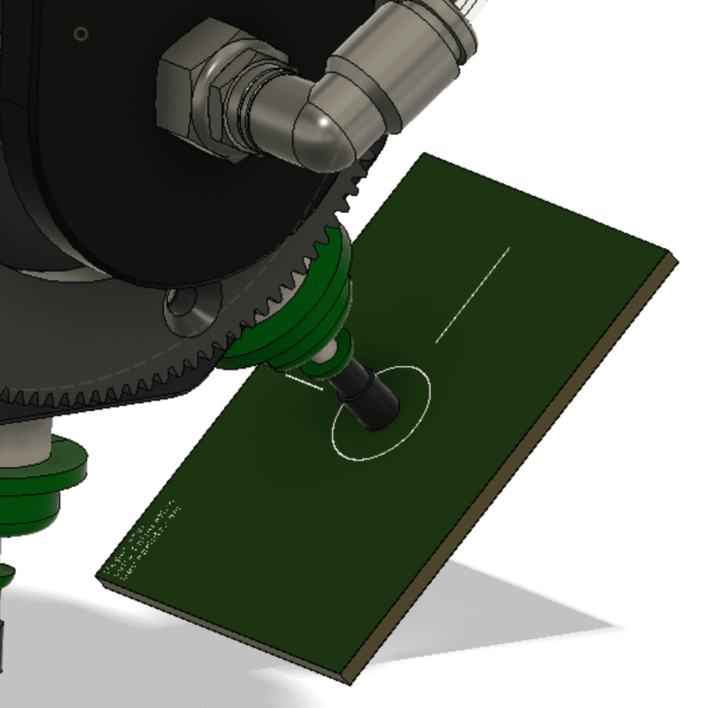
Activate the vacuum pump by clicking on actuators on the jog panel and then turning it on. Attach the PCB that was included with your kit labeled “Lens Calibration” to a 508 nozzle on the head so that the nozzle sits in the center of the circle as shown below, at the same 45 degree angle, ensuring it faces towards the right side of the machine.
Go to Machine Setup > Drivers > Gcode Driver > Console and send the following command:
play /sd/scripts/uplenscalibration.gcode
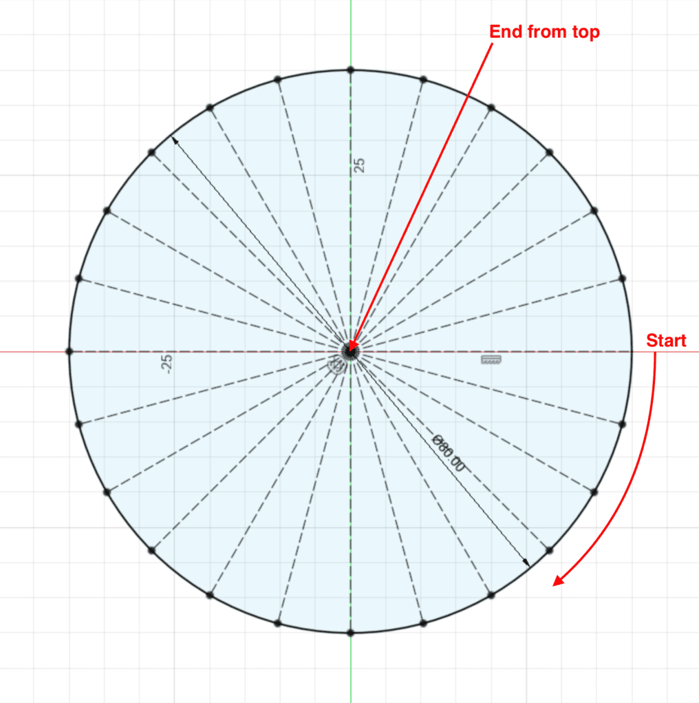
The star will then proceed to pivot the PCB around the upward facing camera and will capture multiple images to calibrate the lens. You will see the screen flash multiple times in OpenPNP when a picture is taken. When the process is complete OpenPnP will enable the undistort function and if all went well your camera view should now appear undistorted. You can toggle the “Apply Calibration” checkbox.
Downward Looking Camera #
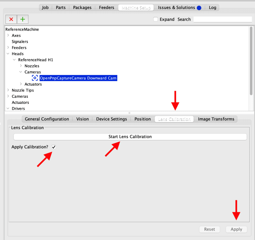
Next we will do the same for the downward looking camera. Take the PCB and hold it in your hands so that the fiducial pattern faces the upward camera. Click Start Lens Calibration and move the PCB around under the camera at various angles until it finishes capturing all the pictures. Make sure all the fiducials are visible in the camera view. Toggle the Apply Calibration checkbox and click Apply to save the settings.
Pixels per mm Calibration #
Upward Looking Camera #
Home the machine and then navigate to Machine Setup > Cameras > Upward Cam > Position. Click the position nozzle icon![]() and the selected nozzle will move above the Upward Camera. Attach a 508 nozzle to the side facing the Upward Camera. Turn on the vacuum and attach the Calibration PCB to the nozzle facing the camera so that the 5×5 square is visible on the camera view as shown below.
and the selected nozzle will move above the Upward Camera. Attach a 508 nozzle to the side facing the Upward Camera. Turn on the vacuum and attach the Calibration PCB to the nozzle facing the camera so that the 5×5 square is visible on the camera view as shown below.
Next go to the Camera Configuration tab, enter 5 for Object Dimensions for both X & Y and click Measure. Position the dashed line over the square as shown below and click Confirm. The Units per PIxel should have now been updated. Click Apply to save the settings. This sets the pixels per mm for the Upward Camera.
Downward Looking Camera #
The Downward Camera gets calibrated the same way. Place the calibration PCB you just used on the conveyor belt so that the 5×5 square faces up. The Calibration PCB should be pushed up against the conveyor with the gripper so it sits at the proper Z height. Jog the head so that the camera is above the PCB and the 5×5 square is visible in the camera view. Next, navigate to Heads > Cameras > Upward Cam > Camera Configuration. Enter 5 for both X/Y and click measure. Position the dashed line over the square and click Measure. Then click apply to save the settings. This sets the pixels per mm for the Downward Camera.
Head Camera Offset #
We now need to tune the camera offsets in X/Y to the selected nozzle. With the Calibration PCB from the previous step still in the conveyor, choose the N1 Nozzle from the jog panel dropdown, load a #503 nozzle and slowly jog it so that it sits in the center of the PCB’s fiducial, touching it (don’t forget you can adjust the jog distance so you don’t crash the nozzle into the pcb).
After you have done that, double check visually that the nozzle sits exactly in the center of the fiducial in X & Y. This is important. Then navigate to Machine Setup > Heads >ReferenceHead H1 > Nozzles > ReferenceNozzle N1 as shown below and click Store nozzle mark position.
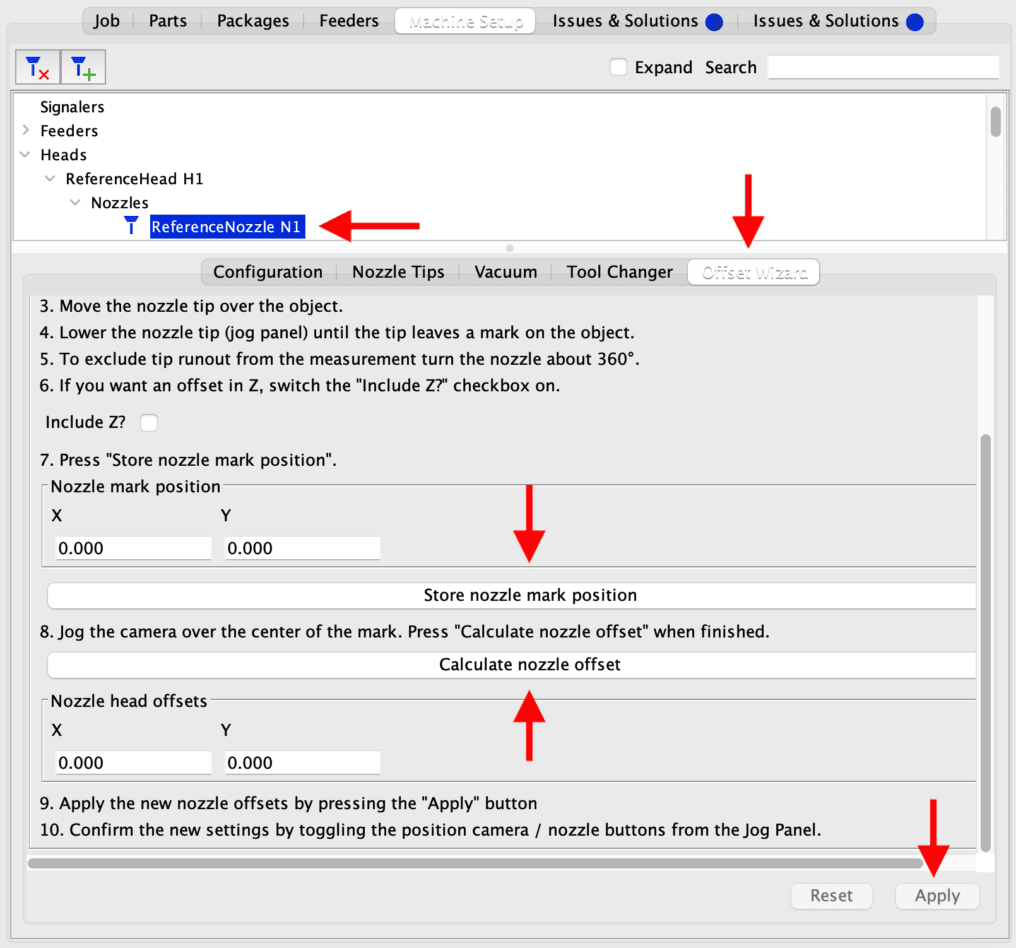
After the nozzle mark position X & Y coordinates were updated, click the park icon ![]() for the Z axis to home the Z. Now jog the downward camera so that the crosshair is over the fiducial. Make sure to carefully align it in the center and click Calculate nozzle offset. The Nozzle head offsets will then update. Click Apply to save the settings.
for the Z axis to home the Z. Now jog the downward camera so that the crosshair is over the fiducial. Make sure to carefully align it in the center and click Calculate nozzle offset. The Nozzle head offsets will then update. Click Apply to save the settings.
To check that your offsets were set correctly, jog the camera over the center of the fiducial and then click the position nozzle ![]() icon in the jog panel. This should bring the nozzle directly over the fiducial. Then click the position camera
icon in the jog panel. This should bring the nozzle directly over the fiducial. Then click the position camera ![]() icon, also in the jog panel, and the camera should move directly over the fiducial. If you notice that the camera is now mis-aligned over the fiducial, then you need to repeat this step. Failure to tune this will cause parts to be placed mis-aligned on your board!
icon, also in the jog panel, and the camera should move directly over the fiducial. If you notice that the camera is now mis-aligned over the fiducial, then you need to repeat this step. Failure to tune this will cause parts to be placed mis-aligned on your board!
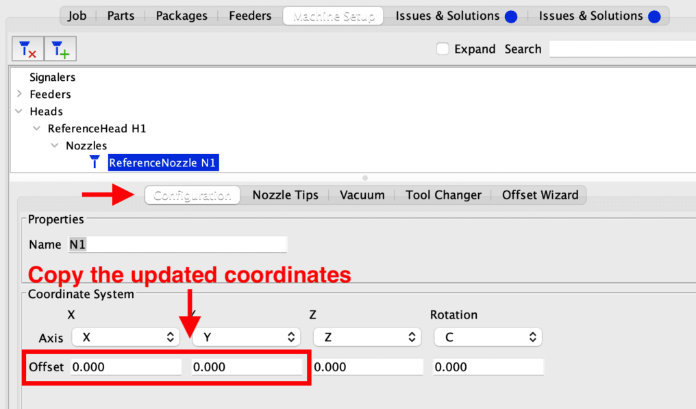
You can then copy the updated coordinates that will show up under the Configuration tab in the X & Y axis fields. Paste these coordinates into the other N2 to N8 nozzles and click Apply to save each nozzle’s offsets as shown below.
Nozzle Magazine Setup #
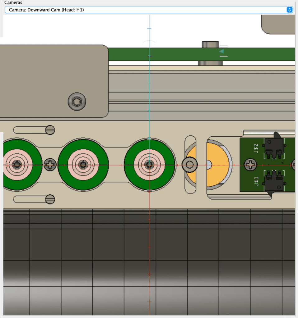
While the nozzle magazine actuator has already been setup for you in OpenpNP, we need to adjust the position of the PCB with limit switches installed on it and all the nozzle positions in OpenPNP. We will first adjust the PCB to make sure the limit switches are triggered every time the magazine is opened and closed.
Slightly un-tighten by just a few turns the two screws holding the PCB so you can move it freely as shown below.
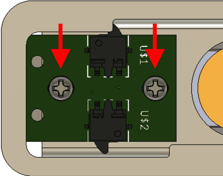
Next, adjust the PCB by moving it very slowly to the left or right and re-tighten the screws (don’t over tighten!) while toggling ON the actuator for the nozzle magazine in the jog panel under Actuators > Nozzle Magazine. If the motor on the nozzle magazine does a full 360o rotation and the cover returns to the same position, it means that one of the end stops isn’t being triggered because the cover cannot reach it. Re-run the adjustment until the cover only opens or closes the nozzles whenever you click ON, on the Nozzle Magazine actuator. Make sure that the cover is fully open and not partially open.
Now that we’ve got the magazine opening and closing the cover properly, we need to adjust the X & Y coordinates in OpenPNP for each nozzle so that the head can pick them up smoothly without crashing into it. Unload all the nozzles from the head to make sure you don’t crash any into the magazine. Navigate to Machine Setup > Nozzle Tips > Click on the first ReferenceNozzle > Tool Changer as shown below.
The distance between the nozzles is 21 mm and there are a total of 20 nozzle holders.
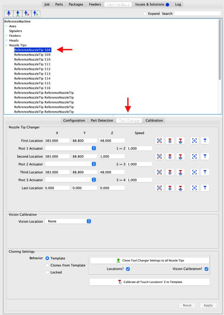
Because these X, Y & Z coordinates vary machine to machine, you need to tune it. If you haven’t loaded the magazine with nozzles, now’s the time to do so. Load them from right to left. It’s ok if you have empty holders in the magazine. We just need to test the first few holders on the right side.
Home the machine in the jog panel ![]() . Select the Down Camera from the cameras dropdown on the jog panel so you can view it and jog it so the crosshair sits directly over the first nozzle all the way on the right side of the machine as shown below.
. Select the Down Camera from the cameras dropdown on the jog panel so you can view it and jog it so the crosshair sits directly over the first nozzle all the way on the right side of the machine as shown below.
For the first location, click the capture camera position icon ![]() and the XYZ coordinates will update.
and the XYZ coordinates will update.
Rapid Feeders #
We have a dedicated guide for the Rapid Feeders. Please have a read and come back here afterwards to continue with the setup.
Trays #
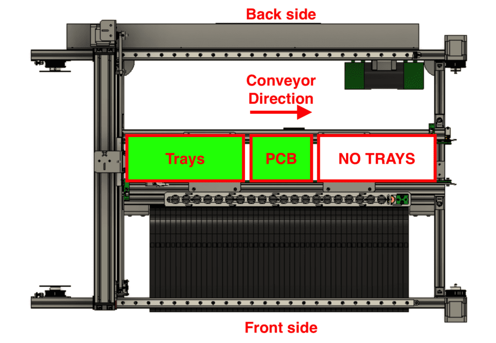
One of the great things about the Rapid Star design is it’s very versatile. You can mount trays anywhere along the conveyor belt using 3D printed brackets secured to the conveyor extrusion for Jedec standard trays or use the included Matrix Tray. Trays should be mounted on the left side of the conveyor before where the board is stopped. This way the empty board can pass under the trays before any components are placed to avoid collision.
Assemble the two included pieces for the Matrix Tray by temporarily using M3 screws with nuts to align and hold the two PCBs together while you solder the two PCBs together.
Note: The tray must be aligned 90 degrees to the X and Y axis when mounted in the machine!
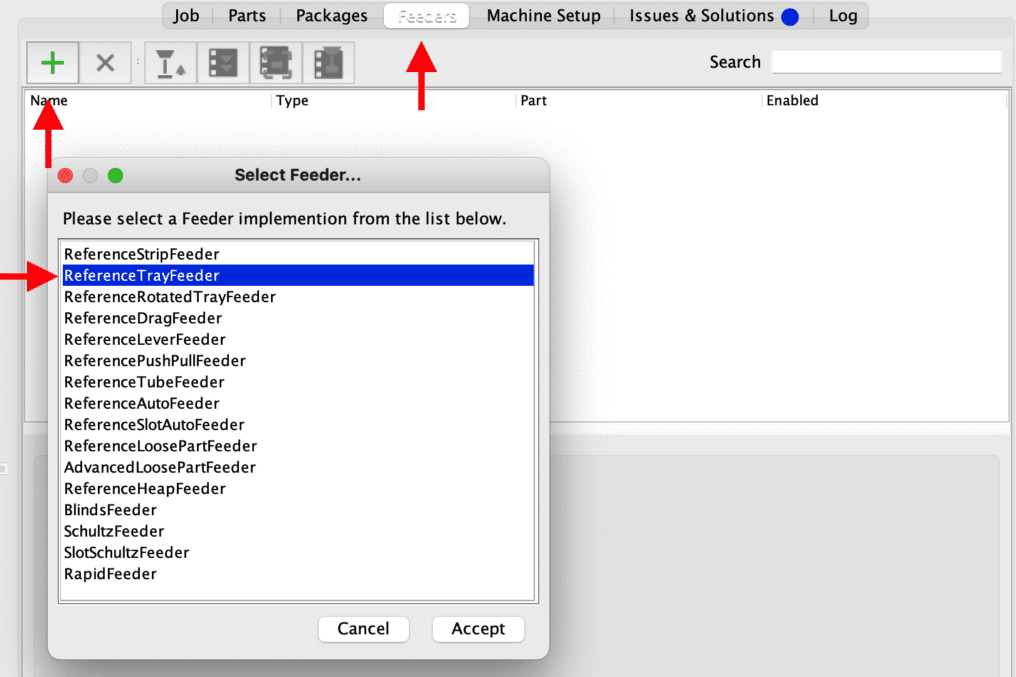
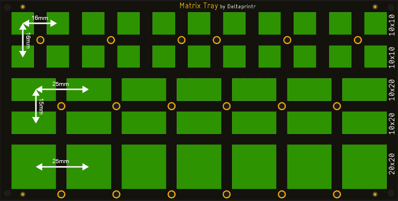
Navigate to Feeders > > ReferenceTrayFeeder and click Accept. This will add a new tray. You can then set up the tray settings. Note that the Matrix Tray included with your Rapid Star is actually a combination of three different trays because of the different size cutouts. Each specific size shaped cutout in the tray needs a ReferenceTrayFeeder set up for it in OpenPNP. To make it easier for you, we’ve included some of the measurements below for each one. You just need to set the first pick location, offsets (based on measurements below) and tray count.
Example: Tray 10×10 has an offset of 16mm in X and 16mm in Y. There are 22 tray counts (square cutouts). Place the component you will put in this section of the tray in the first cutout on the top left. It’s recommended you place components against one of the corners of the cutouts, that way the machine will always pick it in the center of the component. Jog the Downward Cam over the first component you just placed and make sure the crosshair is in the center of the component. Click capture camera position ![]() .You will also have to select the part used in this specific tray from the dropdown list and click Apply to save the settings.
.You will also have to select the part used in this specific tray from the dropdown list and click Apply to save the settings.
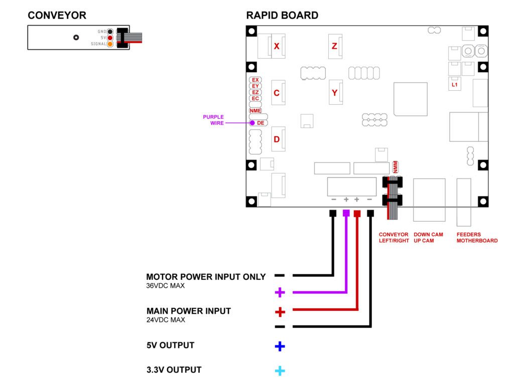
Conveyor #
Discard Location #
Your First Job #
*coming soon*
Supported Commands #
Rapid Star supports all standard Smoothieware firmware Gcode commands. For specific Mcode commands used for various actuators, you can check the config here.
Additional resources #
While this guide covers the basic setup to get your machine running, you can learn about the full spectrum of options that OpenPNP has to offer by checking out the official OpenPNP wiki. There are many useful settings within OpenPNP that you can use to your benefit, which will help speed up your workflow and improve your understanding on how to use the program.


