You may have heard that we’ve been working on the Rapid Feeder for quite some time. It’s taken us longer than expected due to the pandemic, ship delays at ports and supply chain issues worldwide – specifically the semiconductor industry, making it impossible to source ICs and other parts, which forced us to redesign the layout several times.
However, as we are nearing the finish line to finally release the Rapid Feeder, we came upon a new company that has apparently completely knocked off our pre-released design. Not to mention, copied the description from our website as well, word for word. We obtained one of the feeders as we were curious – how is it possible that something which took us so long to prototype and test, still un-released (as of the writing of this post) was already copied, produced and sold for less? Being curious engineers, we dissected the feeder and analyzed it part by part.
Here is our analysis.
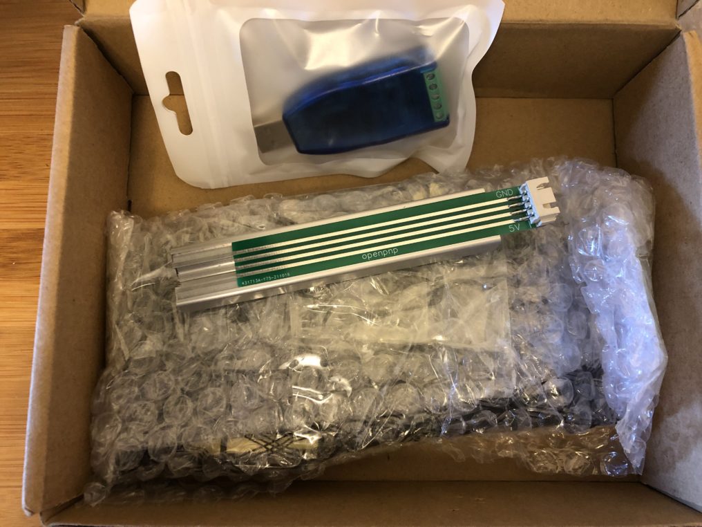
Our first impressions when unboxing the kit is that there’s no instructions included, both on the website and inside the box. You’re pretty much left to figure out how to assemble it on your own. Our guess is that they’re using RS485 since that’s our protocol of choice. In addition, there’s no anti-static bag, so you have no way of knowing if this even works out of the box or if it was damaged due to handling. The blue piece looks to be the RS485-USB converter and without a cable harness. Not to mention, powering it off of USB will kill your computer’s USB port due to excessive current draw (unless your laptop automatically shuts it off). This is why we mention in our setup instructions to power it via 12-24v external power supply.
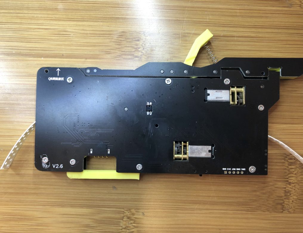
Once the wrapping is removed, this is what it looks like. Immediately we noticed that the mounting design was moved under the feeder and uses a 3D printed part (yellow piece on bottom) that acts as a hinge to lock around the extrusion using a thumb screw. This means anytime you want to swap a feeder out of a bank of 25-50 feeders, you need to spend several minutes reaching under your feeder bank (while strips of SMT tape obstruct your view) and unscrew the hinge using a thumb screw.
The tape’s cover tensioner at the top (yellow piece also) is 3D printed and uses a long spring that can easily fall out. Wether this spring is properly rated for ~160g pull force per EIA-481-E SMT tape industry standards to ensure the cover peels all the way, we don’t know.
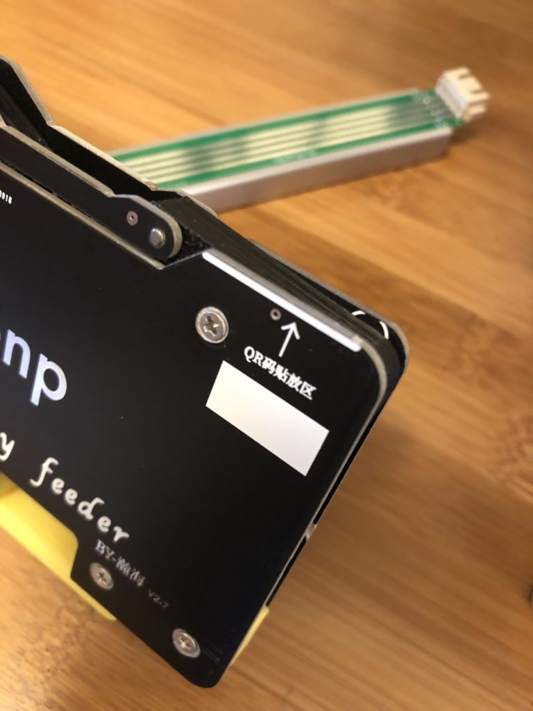
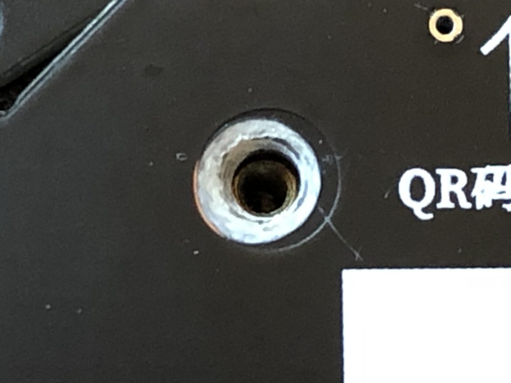
Another feature we noticed is that there appears to be a place holder for a QR code, which we can only presume is for the address of the feeder since that is what the Rapid Feeder uses. It immediately becomes obvious that there’s no way to use this feeder since there’s no address shown!
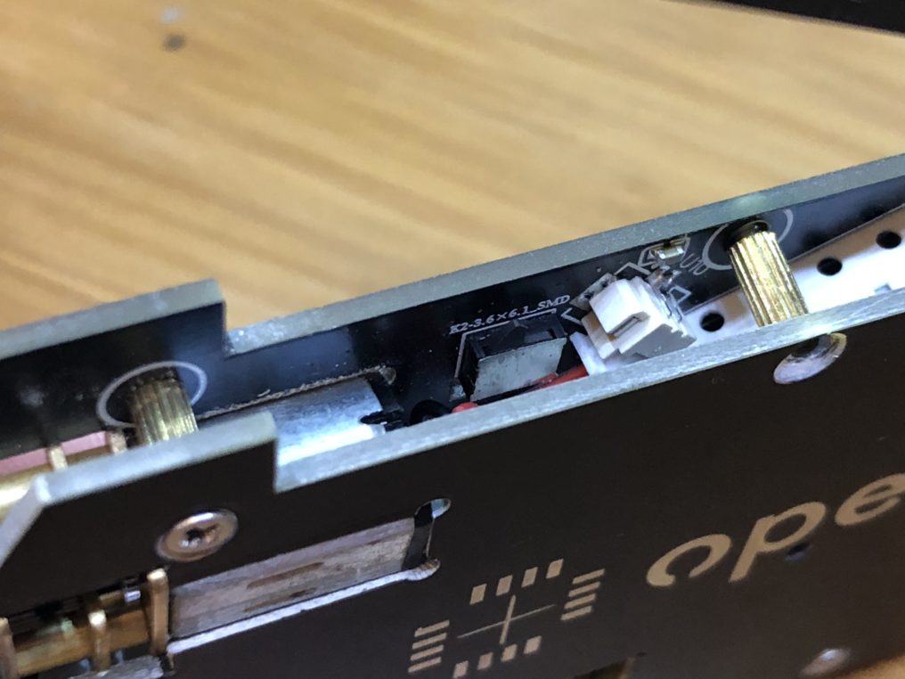
As we were taking it apart, we noticed that the designer(s) opted to use a mechanical limit switch to detect when the cover peeling motor should stop peeling. By the looks of it, they are using something similar to this one, which is rated for 50,000 cycles. The highest rating these can go to is 100,000 cycles at most. Now take into account that a typical passive reel can have up to 5-10K components. This means the switch will stop functioning after just 5-10 reels. Not to mention, they used the wrong switch when choosing Left vs Right switch (they come in two configurations) depending on the direction of actuation.
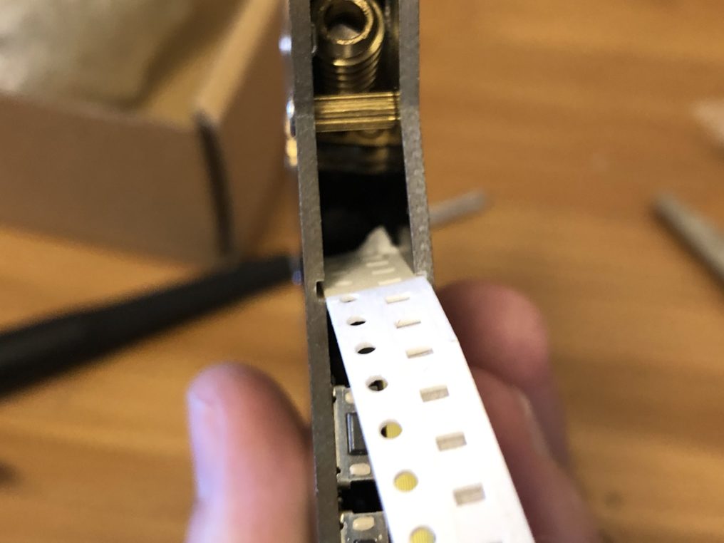
When attempting to insert the tape, we noticed that the width tolerance was larger than the tape width. This means there is good chance of the tape falling through the cavity of the feeder and getting twisted or jammed.
Moving forward, we began unscrewing the screws holding the feeder together and noticed that there are counter bores drilled into the PCB. Why go through the trouble of doing such a complex feature when you can get wafer flat head screws, we’re not sure. But what we did notice is that there is no clearance between the bore and the copper. The metal screw makes direct contact with the copper layer and this occurs in multiple screw holes. Consider what happens when multiple feeder screws make contact with each other or pick up static.
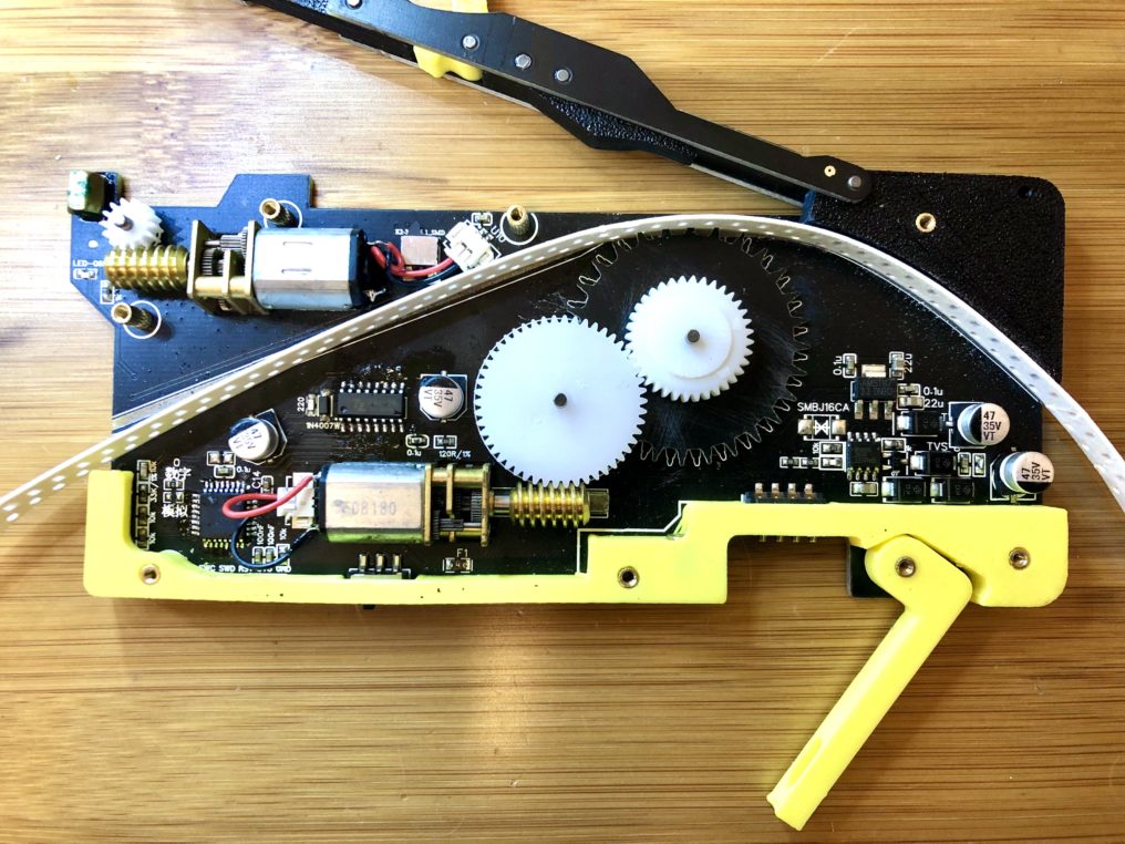
Upon taking the cover off, this is what the internals look like. You can see several 3D printed pieces in yellow and some black parts that (appear to be?) CNC’d plastic. Strange combination of manufacturing processes. Note that the bottom yellow part makes contact with both PCBs. In other words, it acts as a spacer. So if you 3D print 25-50 feeders this way and your print starts to warp, you’ll have varying feeder widths once assembled and is likely (one of) the culprit(s) why the tape falls through.
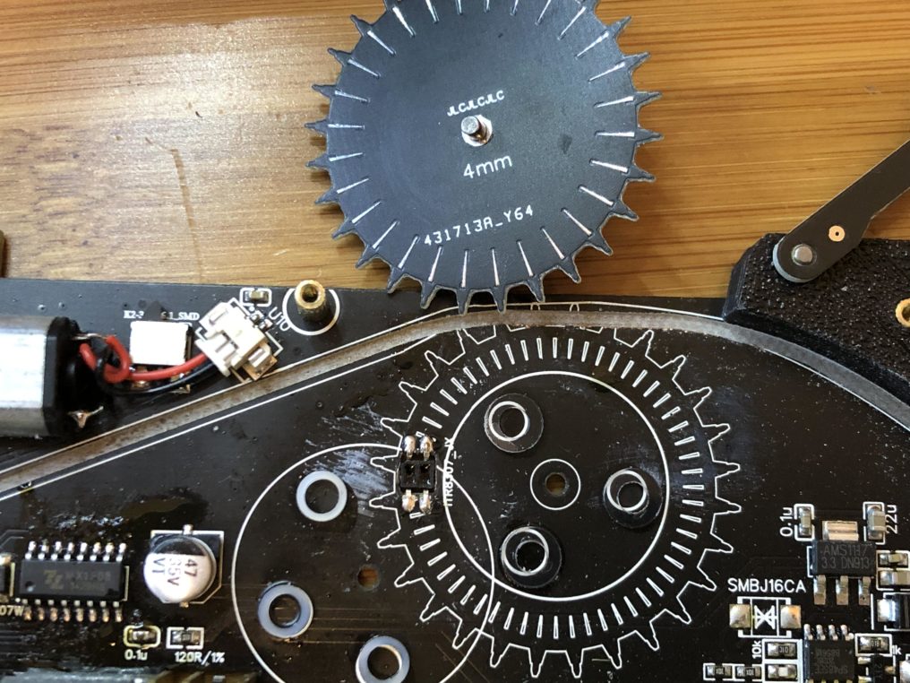
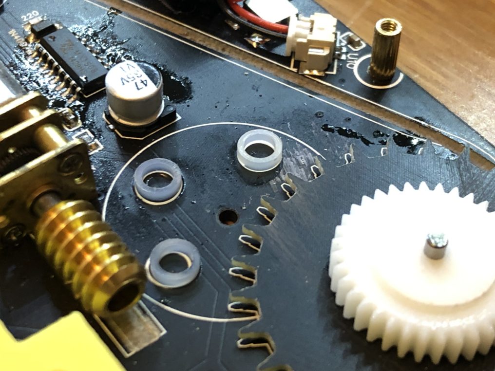
However, what we really wanted to know was, how did they manage to achieve 0402 precision as they had claimed? This was the moment of truth and heart of what makes a precision feeder. We took off the sprocket and mating gear (which we’ll get into shortly) and noticed that they are using a generic reflective sensor, which appears to have been manually pushed into a cutout in the PCB and had its’ legs inverted!
Looking closer, we noticed they had glued spacers to the PCB. Probably to keep the sprocket a minimum distance away from the sensor so the light can reflect off the exposed HASL finish on the sprocket. Not to mention, from the looks of it, the designers attempted to achieve precision by making the HASL extremely thin, hoping that would create a short (…signal?). Not only will this not work at all because it’s barely reflecting off of a large enough surface, but there’s also no cutouts for the light to pass through in the sprocket to break the reflection. It will also reflect off the solder mask just as well! Did we also mention how the spacers will eventually scrape the sprocket and gear, causing the feeder to accumulate plastic dust?
While the spacers may keep the sprocket a minimum distance away from the sensor, it will not keep it a maximum distance away from the sensor, which according to the data sheet on page 3, should be 0.50mm for maximum current output. As a result, because the sprocket can float +/- in distance from the sensor, the time between signals will vary and therefore the distance it moves before it stops.
Side note – you don’t need a “short” position signal to achieve precision. You only need to detect the rising/falling of the encoder at the same threshold to count the steps/distance the tape has traveled.
Looking at the second picture, one can also notice the flux paste has not been washed off the IC.
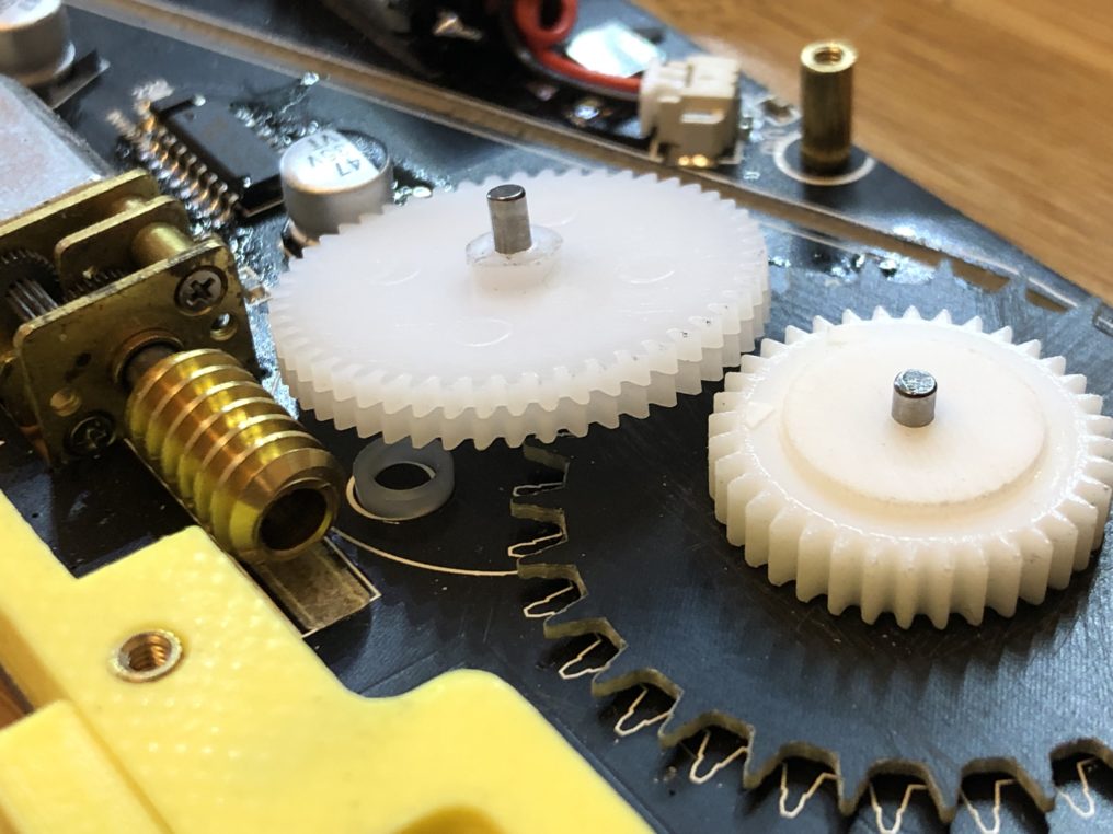
We’ve also noticed how they are using two stacked gears in between the worm gear and sprocket gear. They will just separate from each other during movement and the worm gear will dig in between them.
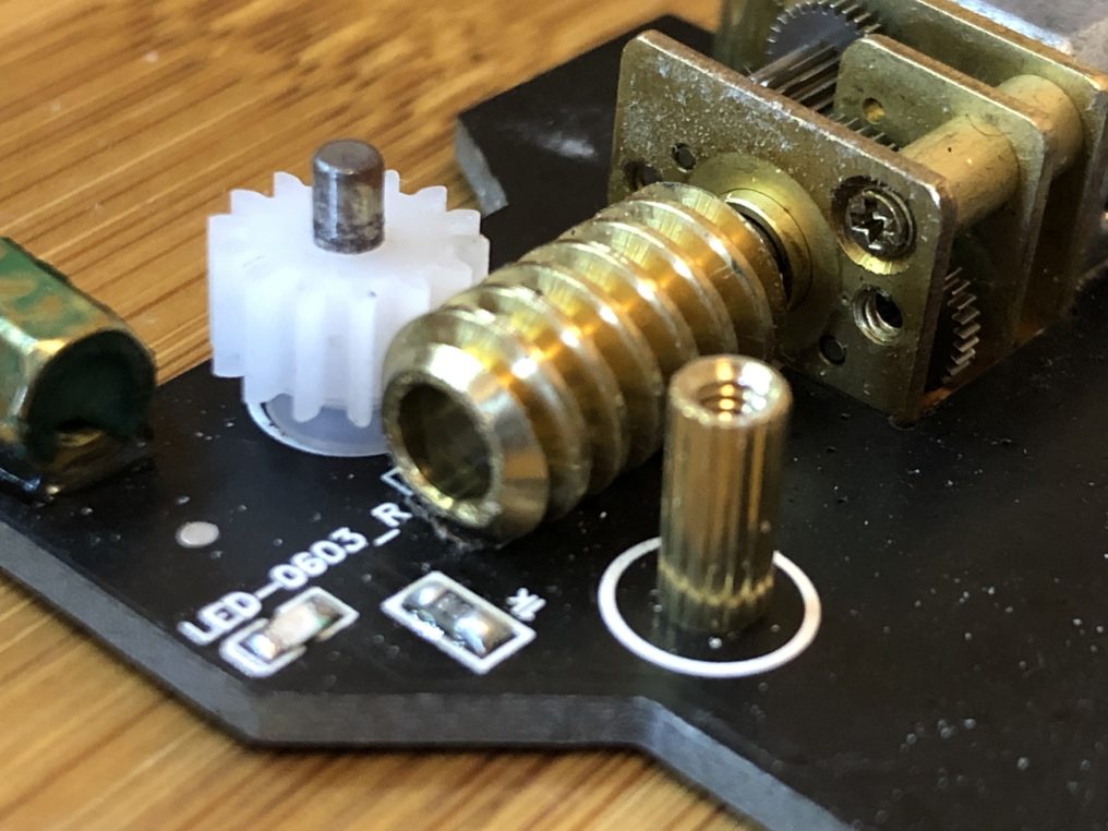
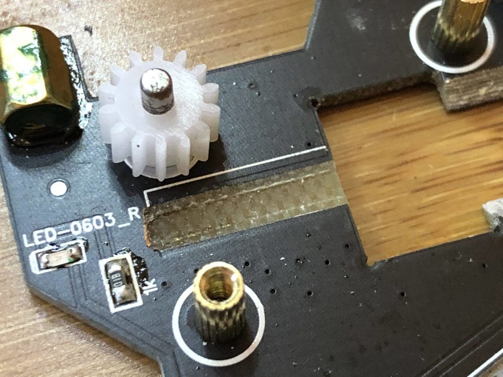
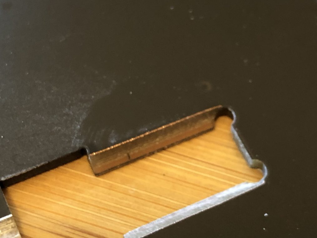
Moving forward we notice more bizarre design decisions. It appears that either for looks or (function?), the designers of this feeder have opted to use a three axis milling process to remove material in a sloped direction around the motor (and again exposing the copper to make contact with the motor). This will absolutely have adverse effects on the function and life span of the feeder as the worm gear rubs against the FR4. Why not just make a cutout as we have done? We may never know.
We can go on and also mention how the idea of using a set screw in this design for adjusting compression between both gears to grip the tape’s cover when peeling it off is a bad idea (think – N20 motor shaft lifespan due to stress and time it takes to adjust 25-50 feeder thumb screws and test), but we think the picture is fairly clear at this point that this feeder will just not function properly.
We’re always excited to see users incorporate our designs into their work and is why we open sourced the Rapid Star PNP so anyone can build a desktop PNP on their own. However, when a company attempts to knock off our design (keyword – knock off, not inspired) and download our entire website’s description of the product word for word, we feel obligated and curious to see how they achieved it. To our expectation, this knockoff was a complete failure and fell short of any effort to improve upon what we’ve already created.
Please consider purchasing directly from creators. Wether that be us or other makers who open source their designs. While you may save a few bucks buying knock offs from websites such as aliexpress or alibaba, in the end it’s not worth the hassle you will have to deal with and hinders the development of open source projects that depend on support from users like you.